General Applications of Electrical Relays
- Basics
- Technology
- Applications
- Standards
- Glossary
Electrical relay ratings
Relay ratings include the coil ratings and contact current ratings.
1. Coil Specification
For actual use, be sure to not exceed the coil rating; it can lead not only to performance loss but also to burn out the coil caused by overvoltage etc. Be sure to carefully select the AC coil specification by checking the applicable power source of each relay (rated voltage, rated frequency).
Certain types of relays may not tolerate under specific rated voltage and rated frequency.
If used under such condition, it can cause abnormal heating and malfunction.
The following chart shows the AC coil specifications.
Example: 100 VAC
| Rating names * | Applicable Power Source (Rated Voltage, Rated Frequency) |
Product Labels | Catalog description |
|---|---|---|---|
| Rating 1 | AC 100V 60Hz | 100VAC 60Hz | AC 100V 60Hz |
| Rating 2 | AC 100V 50Hz, AC 100V 60Hz | 100VAC | AC 100V |
| Rating 3 | AC 100V 50Hz, AC 100V 60Hz AC 110V 60Hz |
100 / 110 VAC, 60 Hz 100 VAC, 50Hz or 100 / (110) VAC |
AC 100 / (110) V |
| Rating 4 | AC 100V 50Hz, AC 100V 60Hz AC 110V 50Hz, AC 110V 60Hz |
100 / 110VAC | AC 100 / 110V |
*Note: that the rating names indicated here are not officially specified by Japanese Industrial Standards (JIS) or the like.
2. Contact Specification
Contact ratings are the standard values for guaranteed relay performance and generally indicates the current rating of the relay contacts.
The rating varies depending on the voltage applied and the types of electrical loads. In other words, the rating includes the specification of the maximum voltage applied to the relay contacts and the maximum current that can be passed to control the electrical load.
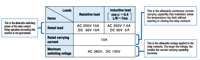
Contact ratings are generally indicated according to resistive loads.
Be sure to choose the right kind of relay applicable to the electrical load you are controlling and that meets your durability requirements.
Electrical relay inrush current
Inrush current is the large current that flows instantaneously when the power is first turned on and supplied to the electrical circuit to control the load, exceeding the steady state current value.
This occurs with electrical loads such as electric motors and incandescent light bulbs.
1. Inrush Current
Resistive load
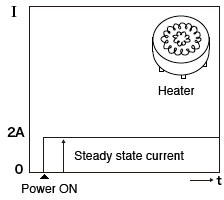
The current remains at constant level immediately after the power is turned on.
Lamp load
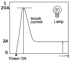
Inrush current of approximately 10 times larger than the steady state current flows immediately after the power is turned on, then returns to its constant level.
2. Inrush Current and Ratings
The TV rating is one of the representative ratings approved by UL and CSA regulations to evaluate the inrush current withstand capability. The rating indicates the level of relay’s capability to switch the load, including the inrush current.
For example, relays for television power supplies need to obtain the TV rating.
TThe switching test (durability test) of these relays is performed using a tungsten lamp as a load and must withstand in total 25,000 times of the durability test.
| TV rating | Inrush current | Steady state current | Example of product types |
|---|---|---|---|
| TV-3 | 51 A | 3 A | G2R-1A G2RL-1A-E-ASI |
| TV-5 | 78 A | 5 A | G5RL-1A(-E)-LN |
| TV-8 | 117 A | 8 A | G4W-1112P-US-TV8 G5RL-U1A-E G5RL-K1A-E G5RL-1A-E-TV8 |
| TV-10 | 141 A | 10 A | G7L |
| TV-15 | 191 A | 15 A | G4A |
DC Circuits
Arc is an electric spark that occurs between the contacts when the relay closes the electric circuit.
As the voltage and current amplitude increase, the arc rises. When the switch is closed slowly, it takes longer time for an arc to form. This can cause the contacts to wear out quickly.
Switching DC circuits
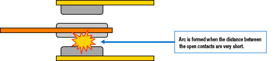
In alternating current (AC), which constantly changes its direction of flow, the arc is quenched every time an overvoltage is delivered.
On the other hand, indirect current (DC) only flows in one direction, which allows forming an arc to take longer, leading to quicker contact wear out and durability decrease.
Also, a transition phenomenon of the contact occurs, which can cause irregularities at the contact points, which can cause malfunctions that can not be separated because they are caught.
Contacts that are connected in series will increase the contact gap in equal length, allowing effective control of the arc.
Minimum load application of electrical relays
A relay may face a problem of contact resistance build-up when switching minimum load applications. Whenever there is a rise in contact resistance, contacts would normally recover by the subsequent operation. Contact resistance may also increase, caused by film formation.
To determine if the measured contact resistance value predicts a relay failure shall depend on whether it is causing a circuit problem or not.
For this reason, only default values are specified as standard failure rates of relay contact resistance. Failure rates (*) are expressed as P level (reference value) as one indicator for minimum applicable loads.
*Notes: Failure rates
The percentage of failures per unit time (or number of operations) during continuous relay switching under individually specified test types and loads.
The rate may vary, depending on the switching frequency, ambient conditions and expected reliability level.
Therefore, users must test the relay under actual operating condition to verify its applicability.
In this catalog, the failure rate is given as the P level (reference value). This expresses the failure level at a reliability level of 60% (λ 60) (JIS C5003).
Using Relays with a Minimum Load Application
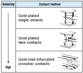
When selecting a suitable relay to switch a minimum load application, be sure to consider the type of load you are switching as well as the required contact material and the contact arrangement.
The contact reliability when controlling minute loads greatly depends on the contact material and contact arrangement.
For example, twin contact points are more reliable than single contact point for minimum load applications simply from the reason that redundancy in parallel operation of twin contact provides greater reliability than is offered by single contact.
Electrical relay durability & life cycle
Durability (life) of a relay is the number of times the relay can switch until it fails to meet the specified values in terms of operating characteristic and performance.
Relay durability is divided into two categories: Mechanical Durability (relay life) and Electrical Durability (relay life).
- Mechanical durability (relay life)
- This is to see how many cycles the relay can operate at the specified switching frequency with no load applied to the contacts.
- Electrical durability (relay life)
- This is to see how many cycles the relay can operate at the specified switching frequency with the rated load applied to the contacts.
Switching Capacity
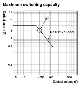
Users shall check the maximum switching capacity of each relay, using graphs to find a relay suitable to their applications.
Maximum switching capacity and durability curve can be used as guidelines for selecting a relay.
Note that the values obtained here are only guidelines; the relay must be tested under actual load condition.
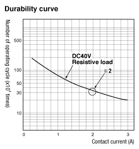
The following shows how to read the graphs of maximum switching capacity and durability curve.
For example, if contact voltage (V1) is already determined, the maximum contact current (I1) can be obtained from the intersection point on the characteristic curve.
Conversely, if the maximum contact current I1 is already determined, contact voltage (V1) can be obtained.
Then the I1 obtained is used to obtain the number of operating cycles from the durability curve.
Example on these graphs:
If contact voltage is 40V,
Contact switching current = 2A …… *1
The number of operating cycle at maximum contact current 2A is approx. 300,000 times …… *2
Maximum switching capacity
Durability curve
Failure Analysis for Electrical Relays
Users may face certain problems associated with relays when operating their equipment.
In such cases, the cause needs to be identified using the FTA (Fault Tree Analysis) method.
The following chart lists specific failure modes and the possible causes.
Problems Visible from Outside the Relay
| Failure events | Checklist | Possible causes |
|---|---|---|
| Relay is not working | 1. Voltage may not be properly applied to the relay input |
|
| 2. Relay specification may not be properly selected for the input voltage being used with it. |
|
|
| 3. There may be input voltage drops. |
|
|
| 4. The relay may be damaged. |
|
|
| 5. The output circuit may not be working properly. |
|
|
| 6. The relay contacts may not be working properly. |
|
|
| No signs of recovery of the relay | 1. The voltage may not be applied to the relay at all. |
|
| 2. Abnormal relay conditions |
|
|
| Relay operation error. Indicator light not functioning properly. |
1. The voltage impressed on the relay input terminal may have exceeded the rated voltage. |
|
| 2. Excessive vibrations or shock may have been applied to the relay. |
|
|
| Burnout | 1. Possible coil burnout |
|
| 2. Possible contact burnout |
|
Problems Visible from Inside the Relay
| Failure events | Checklist | Possible causes |
|---|---|---|
| Contact welding | 1. There may have been a large current flow. |
|
| 2. There may be abnormal vibrations occurring in the contact component. |
|
|
| 3. The relay may have exceeded its contact switching capacity (switching frequency too high). | - | |
| 4. The relay may have reached its end of service life. | - | |
| Contact failure | 1. Foreign materials may be on the contact surfaces. |
|
| 2. There may be possible corrosion of the contact surfaces. |
|
|
| 3. Contact failure may be caused by mechanical damage. |
|
|
| 4. The contacts may be worn out. |
|
|
| Buzzing sound | 1. Voltage applied may not be applied. |
|
| 2. The type of relay may not be properly selected for the application. |
|
|
| 3. The electromagnet may not be working properly. |
|
|
| Abnormal wear of relay contacts | 1. The type of relay may not be properly selected for the application. |
|
| 2. Measures against surge (i.e. surge-absorbing element) need to be taken into consideration when switching the load. |
|
- Basics
- Technology
- Applications
- Standards
- Glossary
Click here for the relay product lineup